Determination of Receding Contact Angle
via Droplet Coalescence (MDC)
SurfaceMeter has recently introduced two dynamic contact angle measurement methods based on liquid bridge interface analysis: the Sliding Liquid Interface method (SLI) and the Needle OUT method (NO). Both approaches enable simultaneous determination of advancing and receding dynamic contact angles. These two values represent the upper and lower limits of the contact angles that a droplet (liquid) may exhibit when wetting a solid surface. Accurate measurement of dynamic contact angles is therefore essential for characterizing surface properties.
The advancing contact angle is highly sensitive to low energy (hydrophobic) surface components. As a droplet expands, its leading-edge struggles to overcome hydrophobic regions, causing the contact angle to increase until the energetic barrier is surpassed. In contrast, the receding contact angle is strongly influenced by high energy (hydrophilic) components. As the droplet contracts, the liquid becomes firmly “pinned” at polar hydrophilic sites. The droplet front resists detaching from these regions, leading to droplet stretching and a pronounced reduction in contact angle, until detachment (de-pinning) finally occurs.
In many cases, accurate determination of the receding contact angle is more challenging than that of the advancing angle. The receding contact angle may refer to the value measured immediately before the liquid/solid three phase contact perimeter (3PCP) begins to retract, during the retraction process, or just after retraction has occurred. These subtle definitional differences are reflected in the measured values. Thus, as with static contact angles, reporting a single numerical value for the receding angle is insufficient. A rigorous measurement report should specify the exact definition used, the relevant measurement parameters, and ideally provide the corresponding measurement curves.
Here we introduce a method available on SurfaceMeter for independently measuring the receding contact angle. Because its principle relies on droplet coalescence to induce 3PCP retraction, we refer to this method as the Method of Droplet Coalescence (MDC). The measurement procedure is as follows, with the coalescence process recorded by video:
Form two separate droplets on the surface (Fig. 1).
Adjust the sample or needle position so that the needle outlet is located between the two droplets (see Fig. 1).
Using the non contact dispensing (NCD) mode, eject a droplet between the two existing droplets. Figure 2 shows the subsequent coalescence process.
Figure 3 compares the images before and after coalescence, clearly showing that the 3PCP retracts after coalescence.
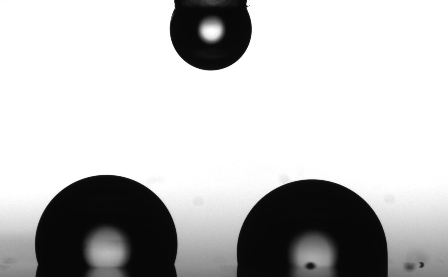 Figure 1: Two separate droplets prior to coalescence, each with a volume of approximately 1.5 μL.
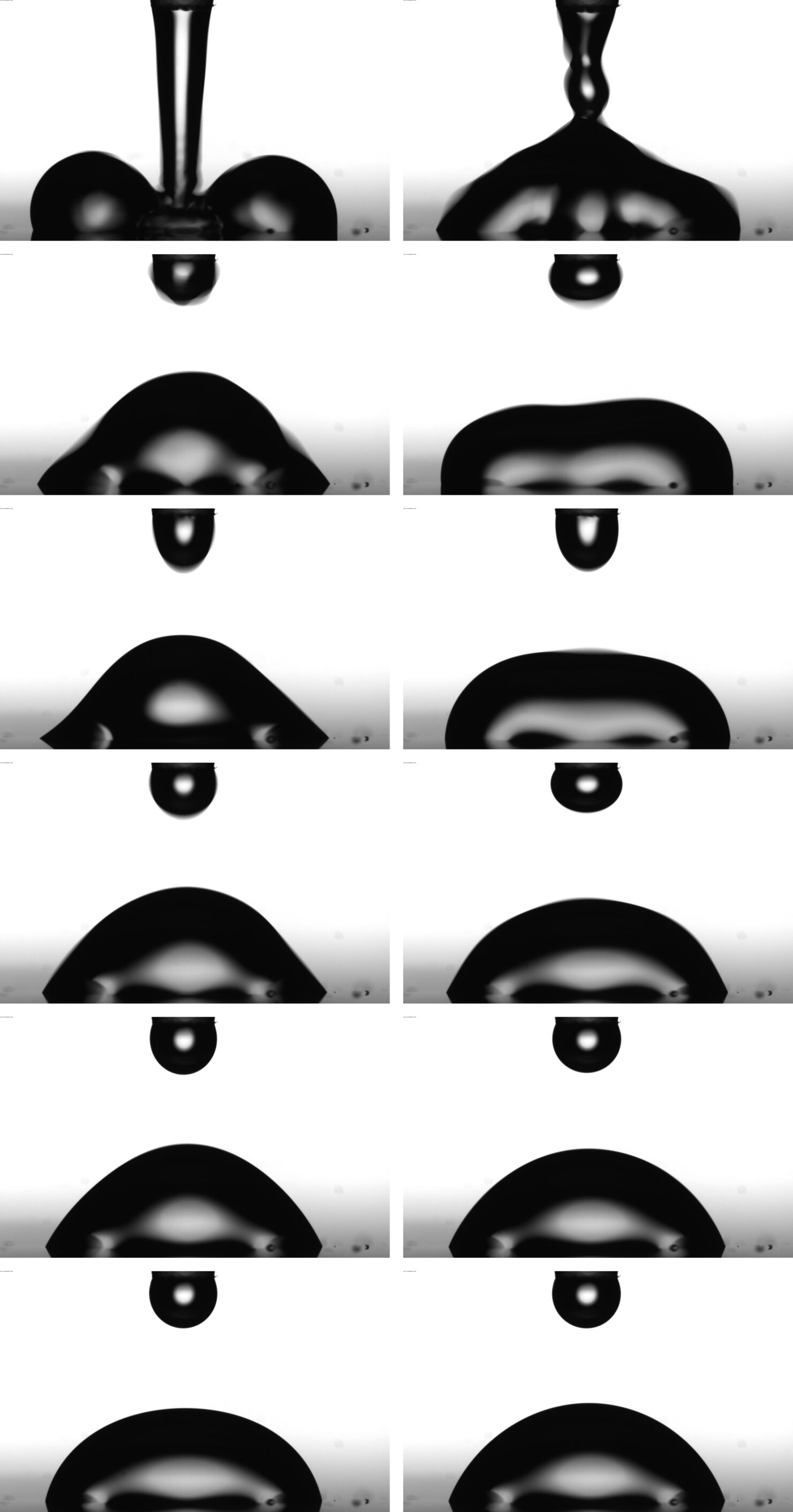 Figure 2: The process of merging the two preceding droplets, induced by jetting a droplet with a volume of approximately 1.5 µL.
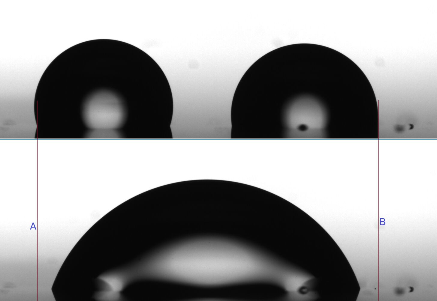 Figure 3: Comparison of the liquid/solid-contact triple-phase contact line (3PCP) positions before and after droplet coalescence
The recorded video is analyzed using Method ONE, and the results are shown in Fig. 4. The first frame suitable for calculation appears approximately 13ms after the ejected droplet touches the two pre existing droplets (the touch occurs at 588ms on the time axis in Fig. 4). After contact, the droplet begins to oscillate due to the kinetic energy delivered by the ejected droplet, causing retraction of the 3PCP. During this process, the contact angle oscillates; the contact diameter initially decreases rapidly and reaches a stable value about 200ms after coalescence begins. The corresponding contact angle of 70.3° can be regarded as the receding contact angle after 3PCP retraction.
Subsequently, the contact diameter decreases slowly, indicating continued slow retraction of the droplet. The contact angle increases gradually from 70.3° to 71.8° over approximately 2.8 s. Figure 5 shows the droplet image and calculated results after about 10 minutes, at which point the contact angle has increased to 80.5°, and the contact diameter has decreased to 2.438 mm (the final value in Fig. 4 is 3.058 mm). The contact angle curve in Fig. 4 also shows that during the initial oscillation phase after impact, the contact angle may fall below the receding angle. However, the internal force distribution within the droplet during this highly dynamic, non uniform state is complex and cannot be compared with the typical droplet state during steady retraction (see Fig. 8).
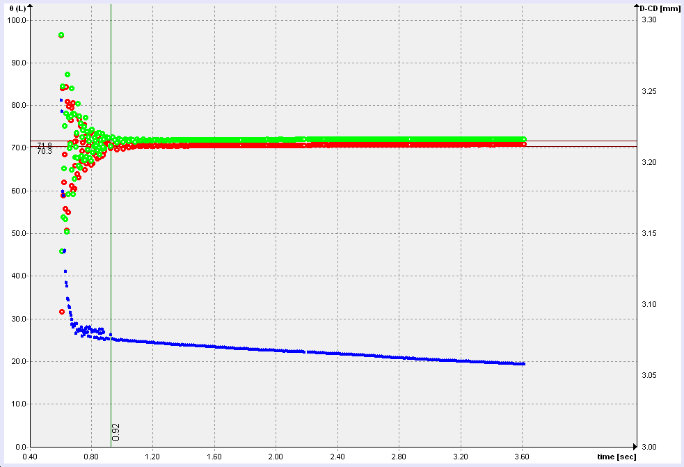 Figure 4: Computational results for the droplet coalescence process: the red and green curves correspond to the contact angle values on the left and right sides, respectively; the blue curve (right axis) represents the contact diameter.
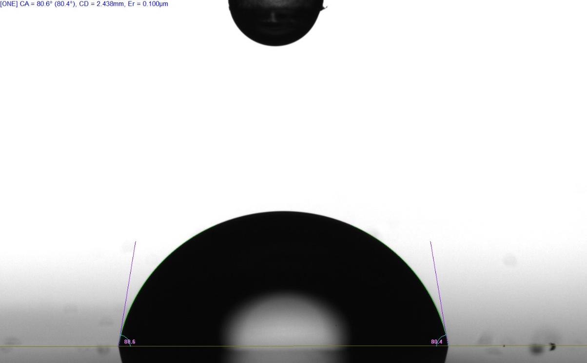 Figure 5: Images and calculation results approximately 10 minutes after the onset of the coalescence process; contact diameter = 2.438 mm.
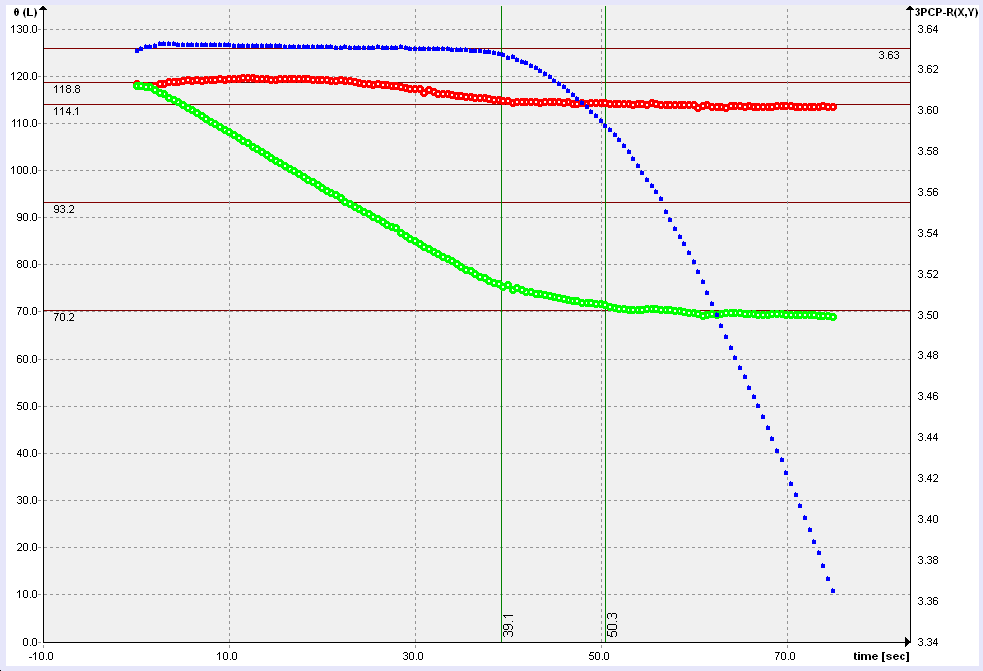 Figure 6: Results obtained using SLI (movement speed 1 mm/min). The red and green curves correspond to the contact angle values on the advancing and receding sides of the liquid bridge, respectively; the blue curve (right axis) represents 3PCP on the receding side
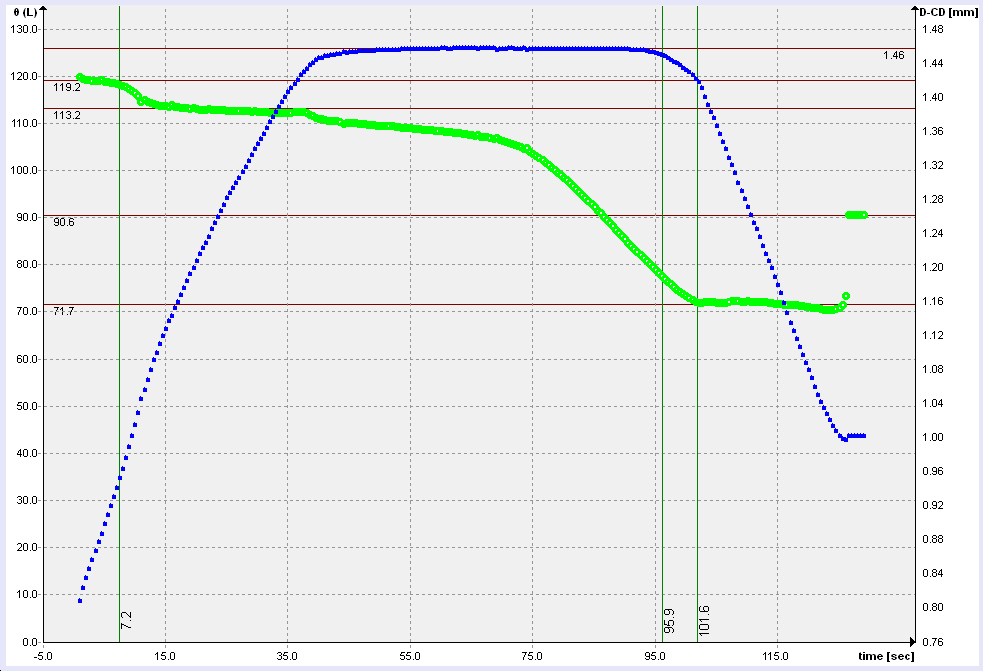 Figure 7: Results obtained using the liquid bridge volume increase/decrease method (NO) with a dosing rate of 2 µL/min: the green curve represents the average contact angle at both sides of the liquid bridge, while the blue curve (right axis) shows the variation in the three-phase contact diameter.
For comparison, dynamic contact angle measurements were performed at different positions on the same sample using the SLI (Sliding Liquid Bridge Interface) and NO (liquid bridge volume increase/decrease) methods. Figures 6 and 7 show the results.
The advancing contact angle of this sample initially measures approximately 119°, then decreases to about 113–114°. The receding contact angle plateau values are 70.2° (SLI) and 71.7° (NO). Considering the inherent non uniformity of the sample surface, these values are essentially consistent with the 70.3° obtained using MDC.
Careful examination of the 3PCP position curves reveals that the contact angle at the moment of 3PCP retraction is about 5° higher than the final plateau value. The receding contact angle depends on the retraction speed of the 3PCP: higher retraction speeds yield lower values. This again illustrates that reporting a single receding contact angle without specifying the measurement method, parameters, and determination procedure renders the value incomparable and less meaningful.
The final contact angle of 90.6° in Fig. 7 corresponds to the sessile droplet formed on the surface after the liquid bridge breaks.
The Method of Droplet Coalescence (MDC) is characterized by the following features:
No foreign solid surfaces are involved during measurement. Apart from the liquid and the solid sample surface, no additional solid objects (such as needles or capillaries) interfere with the droplet. Retraction of the three phase contact perimeter (3PCP) occurs solely through the interplay of the liquid surface tension (γL), the interfacial tension between the liquid and the solid sample surface (γLS), and the solid surface free energy (γS). The kinetic energy delivered by the ejected droplet enables the system to overcome the energy barrier (see Fig. 8), allowing it to enter a higher energy metastable configuration (the state labeled “RCA” in Fig. 8), in which the receding contact angle is exhibited. Because this state is energetically elevated, the system spontaneously evolves toward lower energy configura-tions in the absence of continuous external forcing, manifested as a slow increase in contact angle over time. However, during this evolution, the system is also constrained by local energy barriers (the red arrow and “energy barrier” label in Fig. 8), making it difficult for the droplet to reach the global minimum energy, fully stable state.
This method can only be used to measure the receding contact angle; it cannot simultaneously determine the advancing angle.
The consistency of the receding contact angle values obtained using three different methods further demonstrates that the receding angle corresponds to a physically real and accessible system state. Although the measurement principles and probes differ, all appropriate methods are capable of detecting the contact angle associated with this state.
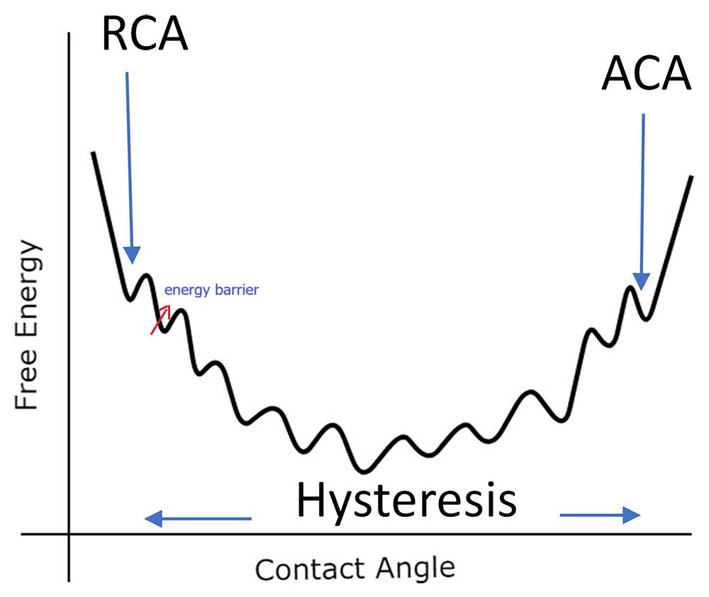 Figure 8: Relationship between Contact Angle and System Free Energy ACA/RCA = Advancing/Receding Contact Angle